- 您现在的位置:买卖IC网 > Sheet目录1869 > PCA85132U/2DB/Q1,0 (NXP Semiconductors)IC LCD DRIVER 32 UNCASED
�� �
�
�NXP� Semiconductors�
�PCA85132�
�LCD� driver� for� low� multiplex� rates�
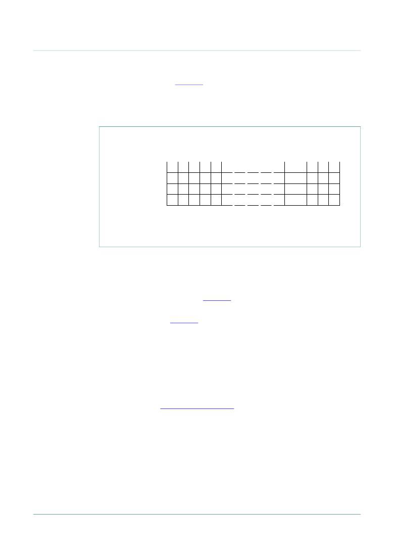
�The� display� RAM� bitmap,� Figure 12� ,� shows� the� rows� 0� to� 3� which� correspond� with� the�
�backplane� outputs� BP0� to� BP3,� and� the� columns� 0� to� 159� which� correspond� with� the�
�segment� outputs� S0� to� S159.� In� multiplexed� LCD� applications� the� segment� data� of� the�
�first,� second,� third,� and� fourth� row� of� the� display� RAM� are� time-multiplexed� with� BP0,�
�BP1,� BP2,� and� BP3� respectively.�
�columns�
�display� RAM� addresses/segment� outputs� (S)�
�rows�
�0�
�1�
�2�
�3�
�4�
�155� 156� 157� 158� 159�
�0�
�display� RAM� rows/�
�backplane� outputs� 1�
�(BP)�
�2�
�3�
�013aaa220�
�The� display� RAM� bitmap� shows� the� direct� relationship� between� the� display� RAM� addresses� and�
�the� segment� outputs;� and� between� the� bits� in� a� RAM� word� and� the� backplane� outputs.�
�Fig� 12.� Display� RAM� bitmap�
�When� display� data� is� transmitted� to� the� PCA85132,� the� received� display� bytes� are� stored�
�in� the� display� RAM� in� accordance� with� the� selected� LCD� drive� mode.� The� data� is� stored� as�
�it� arrives� and� does� not� wait� for� the� acknowledge� cycle� as� with� the� commands.� Depending�
�on� the� current� multiplex� drive� mode,� data� is� stored� singularly,� in� pairs,� triples,� or�
�quadruples.� To� illustrate� the� filling� order,� an� example� of� a� 7-segment� numeric� display�
�showing� all� drive� modes� is� given� in� Figure 13� .� The� RAM� filling� organization� depicted�
�applies� equally� to� other� LCD� types.�
��?� In� static� drive� mode� the� eight� transmitted� data� bits� are� placed� in� row� 0� as� 1� byte.�
�?� In� 1:2� multiplex� drive� mode� the� eight� transmitted� data� bits� are� placed� in� pairs� into�
�row� 0� and� 1� as� 2� successive� 4-bit� RAM� words.�
�?� In� 1:3� multiplex� drive� mode� the� 8� bits� are� placed� in� triples� into� row� 0,� 1,� and� 2� as� 3�
�successive� 3-bit� RAM� words,� with� bit� 3� of� the� third� address� left� unchanged.� It� is� not�
�recommended� to� use� this� bit� in� a� display� because� of� the� difficult� addressing.� This� last�
�bit� may,� if� necessary,� be� controlled� by� an� additional� transfer� to� this� address� but� care�
�should� be� taken� to� avoid� overwriting� adjacent� data� because� always� full� bytes� are�
�transmitted� (see� Section� 7.5.3� on� page� 25� ).�
�?� In� 1:4� multiplex� drive� mode,� the� eight� transmitted� data� bits� are� placed� in� quadruples�
�into� row� 0,� 1,� 2,� and� 3� as� 2� successive� 4-bit� RAM� words.�
�PCA85132�
�Product� data� sheet�
�All� information� provided� in� this� document� is� subject� to� legal� disclaimers.�
�Rev.� 3� —� 11� July� 2013�
�?� NXP� B.V.� 2013.� All� rights� reserved.�
�22� of� 62�
�发布紧急采购,3分钟左右您将得到回复。
相关PDF资料
PCA85134H/Q900/1,1
IC LCD DRIVER 80-LQFP
PCA85162T/Q900/1,1
IC LCD DRIVER 32 SEG 48TSSOP
PCA85176H/Q900/1,5
IC LCD DRIVER 40SEG 64TQFP
PCA8534AH/Q900/1,5
IC LCD DRIVER 60SEG 80LQFP
PCA8536BT/Q900/1,1
IC LCD DRIVER LOW MPLEX 56TSSOP
PCA8576CH/Q900,157
IC LCD DRIVER UNIV 64LQFP
PCF1175CT/S420/2:1
IC LCD CAR CLOCK 4DIGIT 28SOIC
PCF1178CT,112
IC LCD CAR CLOCK 4DIGIT 28SOIC
相关代理商/技术参数
PCA85133
制造商:PHILIPS 制造商全称:NXP Semiconductors 功能描述:Universal LCD driver for low multiplex rates
PCA85133U/2DA/Q1
制造商:PHILIPS 制造商全称:NXP Semiconductors 功能描述:Universal LCD driver for low multiplex rates
PCA85133U/2DA/Q1,0
功能描述:IC LCD DRIVER UNIV UNCASED RoHS:是 类别:未定义的类别 >> 其它 系列:* 标准包装:1 系列:* 其它名称:MS305720A
PCA85133U/2DB/Q1
制造商:PHILIPS 制造商全称:NXP Semiconductors 功能描述:Universal LCD driver for low multiplex rates
PCA85133U/2DB/Q1,0
功能描述:IC LCD DRIVER UNIV UNCASED RoHS:是 类别:未定义的类别 >> 其它 系列:* 标准包装:1 系列:* 其它名称:MS305720A
PCA85133U/2DB/Q1,026
制造商:NXP Semiconductors 功能描述:0
PCA85134
制造商:PHILIPS 制造商全称:NXP Semiconductors 功能描述:Smart, simple solutions for the 12 most common design concerns
PCA85134H/Q900/1,1
功能描述:LCD 驱动器 60 X 4 LCD DRIVER FOR MULTIPLEX RATES RoHS:否 制造商:Maxim Integrated 数位数量:4.5 片段数量:30 最大时钟频率:19 KHz 工作电源电压:3 V to 3.6 V 最大工作温度:+ 85 C 最小工作温度:- 20 C 封装 / 箱体:PDIP-40 封装:Tube